Architecture and Components of Raster-Scan and Random-Scan Systems
On this page (4sections)
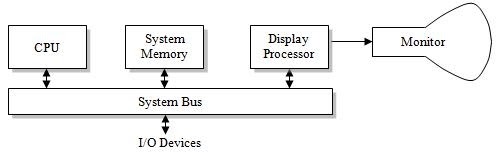
Interactive raster-graphics systems typically employ several processing units. In addition to the CPU, a special purpose processor called the video controller or display controller is used to control the operation of the display device.
The figure shows the organization of a raster system. The frame buffer can be anywhere in the system memory, and the video controller access the frame buffer to refresh the screen.
Video Controller
The video controller plays a crucial role in raster-scan systems. It is allocated a dedicated portion of the system memory known as the frame buffer, which it directly accesses to refresh the screen. The coordinate system of the graphics monitor begins at the lower left corner, with positive x values increasing to the right and y values increasing from bottom to top.
To understand the refresh operation of the video controller, let’s examine the diagram below:
The video controller employs two registers to store the coordinates of the screen pixels. Initially, x = 0 and y = ymax (the maximum y-coordinate). The video controller retrieves the pixel value stored in the frame buffer corresponding to this pixel position. Then, it increments the x value by 1 and retrieves the corresponding y value. This process continues, retrieving pixel values line by line. Once the last pixel is reached, the registers are reset to their initial values, and the process repeats.
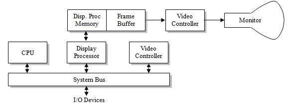
Display Processor
The display processor, also known as the graphics controller, plays a vital role in offloading graphics-related tasks from the CPU. In addition to the system memory, a separate display processor memory area can be provided.
One of the primary tasks of the display processor is scan conversion, which involves digitizing a picture definition from an application program into a set of pixel-intensity values stored in the frame buffer. Geometric objects, such as lines, are converted into sets of discrete intensity points. Characters can be defined using rectangular grids or curved outlines.
To optimize memory usage, scan lines are often stored as sets of integer pairs. Each pair consists of an intensity value and the number of adjacent pixels on the scan line that have the same intensity. This compression technique is known as run-length encoding.
By employing the display processor, the CPU is freed from handling graphics-related operations, allowing it to focus on other tasks.
Random-scan Systems
In random-scan systems, an application program is inputted and stored in the system memory alongside a graphics package. Graphics commands within the program are translated by the graphics package into a display file, which is then stored in the system memory. The display processor accesses this display file to refresh the screen. During each refresh cycle, the display processor cycles through each command in the display file program.
The display processor in a random-scan system is sometimes referred to as a display processing unit or a graphics controller.
To draw graphic patterns on a random-scan system, the electron beam is directed along the component lines of the picture. Lines are defined by specifying the coordinates of their endpoints. These input coordinate values are then converted into x and y deflection voltages. The scene is drawn one line at a time, with the beam positioned to fill in the line between the specified endpoints.
By understanding the architecture and components of raster-scan systems and random-scan systems, we gain insight into the inner workings of interactive graphics systems, which play a significant role in various applications such as computer-aided design, gaming, and multimedia.